Safety Warning
Power Adapter
Input:
AC 100V ~ 240V, 50/60Hz; @0 .8A
Output: DC 5V, 1A , USB Type-C
Use the power adaptor in strict accordance with the specifications , or it may cause damage to the device .
Battery
The internal part of the instrument is a lithium battery. In order to give full play to the performance of the battery, when using
the instrument for the first time , please use the internal battery to supply power. After the battery runs out , charge the
battery then .
The first charging time should not be less than 5 hours . The charging temperature range of the battery in the instrument is
10o
C~50o
C . When temperature is too high , please stop charging for safety.
When the instrument is idle for more than 3 months , it should be charged in time to maintain the battery power. The
temperature range of battery for long-term storage is- 20o C~45o C .
Do not take out the battery without permission . Please keep the battery away from the fire source and strong heat; Do not
open or damage the battery.
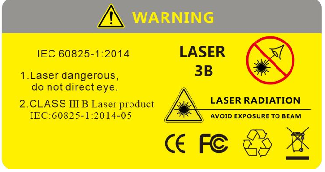
Laser Safety Instruction
The laser safety level of this instrument is CLASS IIIB , which is harmful to human body. Please pay attention to safety
during use
Safety WarningWhen using this instrument , please avoid looking directly at the laser output port , and do not look directly at the end of the
optical fiber when testing; When the instrument is used , please cover the dust cap of the light output port . W hen the visible
red light function of the instrument is turned on , please do not look directly at the output port of the red light source or the
tail end of the optical fiber connected to the red light output port , so as to avoid eye injury.
 KeyParts
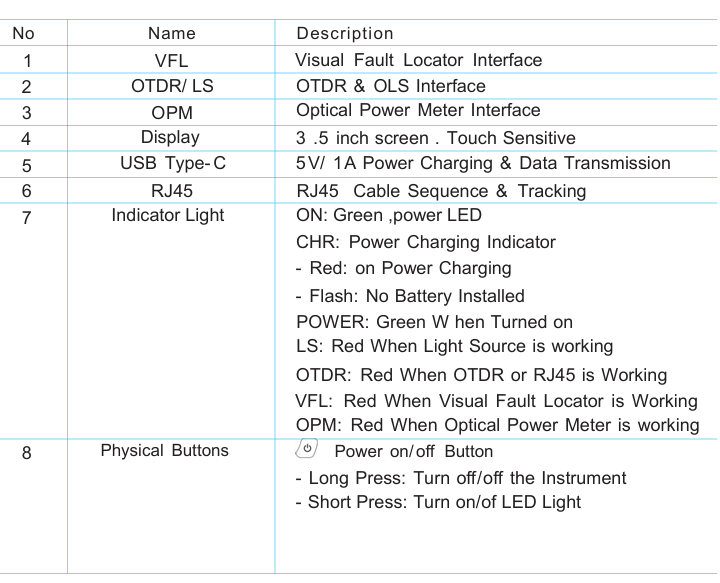
KeyParts
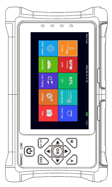
Booting up your New Instrument
Turn on the instrument
Press [POWER] button to start the instrument . The instrument will go into
welcome page . Then after around 2 seconds , it will arrive the main page
with all functions .
Turn on or off LED light
After the instrument was turned on , press [ Power] to turn on LED light or
turn off LED light . LED Light is at back of the instrument .
Turn off the instrument
Long press [POWER] button to turn off the instrument .
Enter a particular function
Use [Navigation] Button to select the function you are going to enter. and
press [OK] button to enter the selected button . When first function is
selected , only [RIGHT] and [DOWN] navigation buttons are allowed to
operating . [LEFT] and [UP] buttons are prohibited . When last function is
selected , only [LEFT] and [UP] buttons are allowed to operating . [RIGHT]
and [DOWN] buttons are prohibited .
Exit from a particular function
After you entered a particular function , press [ESC] to exit from the
function and come back to main page
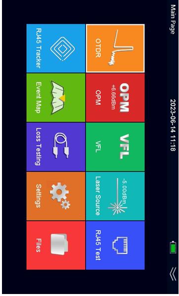
Main Page
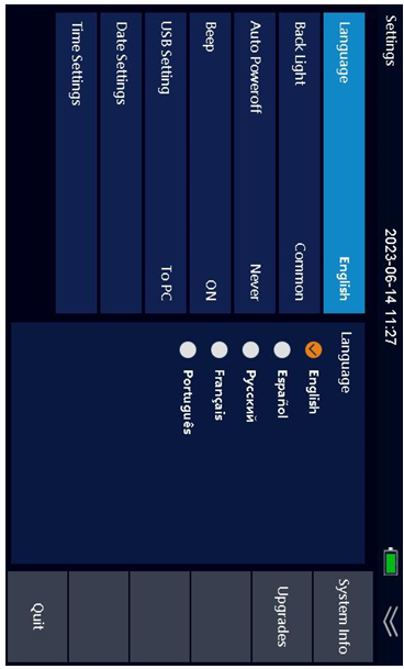
System SettingBy [Navigation] to select System , press [OK] button to enter the function .
Language Selection
Press [UP] or [DOWN] button to select Language , then press [OK] button
to call out Languages Menu . Press [UP] or [DOWN] button to select target
language .
Auto Power off
Press [UP] or [DOWN] button to select Auto Power off , then press [OK]
button to call out Power off Menu . Press [UP] or [DOWN] button to select
target auto- power-off time .
Beep
Press [UP] or [DOWN] button to select Beep , then press [OK] button to
turn on or off beep sound .
USB Connection
Press [UP] or [DOWN] button to select Beep , then press [OK] button to
turn on or off beep sound .
Touch Screen
Press [UP] or [DOWN] button to select Touch Screen , then press [OK]
button to turn on or off touch screen .
Date & Time
Press [UP] or [DOWN] button to select Touch Screen , then press [OK]
button to set date & time
System
OTDR SettingBy [Navigation] to select OTDR , press [OK] button to enter the function .
Before you start testing a fiber, please complete setting work . Press
[LEFT] or [RIGHT] button to select setting menu , then press [OK] button
to enter into setting .
Wavelength
Press [UP] or [DOWN] button to select Wavelength , then press [OK]
button to call out Wavelength Menu . Press [ UP] or [DOWN] button to
select target 1310nm , 1550nm , 1610nm , 1625nm , 1650nm . Different
model number is with different wavelengths available .
Test Mode
Press [UP] or [DOWN] button to select Test Mode , then press [OK] button
to select Auto or Manual
What is different between Auto and Manual mode?
Auto mode: The instrument will automatically set the most appropriate
parameters for the current measurement , and the measurement
range and pulse width selected values cannot be modified at this time .
Manual mode: The range and pulse width can be set manually
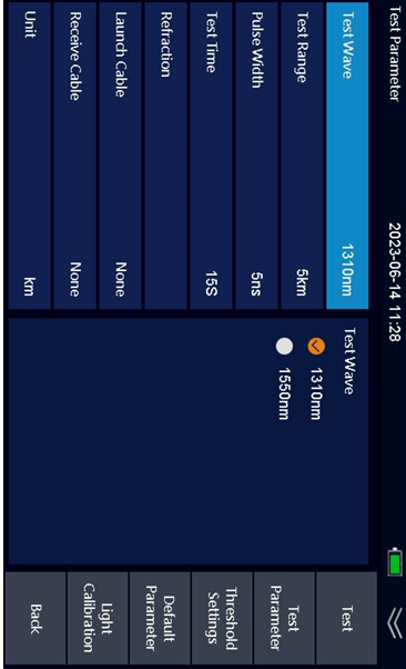
OTDR Testing Parameter
OTDR SettingTest Range
Press [UP] or [DOWN] button to select Test Range , then press [OK] button to select target Test Range . The optional test
range is 100m/ 500m/ 2 km/ 5 km/ 10km/ 20km/ 40km/ 60km/ 90km .
Pulse Width
Press [UP] or [DOWN] button to select Pulse Width , then press [OK] button to call out Pulse Width Menu . Press [UP] or
[DOWN] button to select target Pulse Width . The optional pulse width is 5ns/ 10ns/ 20ns/ 50ns/ 100ns/ 200ns/ 500ns/1 us/ 2
us/ 5 us/ 10us/ 20us .
Test Time
Press [UP] or [DOWN] button to select Test Range , then press [OK] button to select target Test Time .
Refraction
Press [UP] or [DOWN] button to select Refraction , then press [OK] button to enter Refraction Value setting . Input refraction
value .
Event Threshold
Press [UP] or [DOWN] button to select Event Threshold , then press [OK] button to enter Event Threshold setting . Input
event threshold value .
End Loss Threshold
Press [UP] or [DOWN] button to select Event Threshold , then press [OK] button to enter Event Threshold setting . Input
event threshold value .
Default
Press [SHIFT] button to change operation area from top menu to bottom menu , then press [OK] button to confirm if you are
going to change all settings above to be back to factory default setting
OTDR SettingLight Calibration
Press [RIGHT] button to select Light Cal menu , then press [OK] to confirm light calibration .
Back
Press [ESC] button to select Back Menu , then press [OK] to come back OTDR . You can also use [ESC] button to process
the same operation .
Before OTDR TestingFiber preparation
The Smart OTDR works on any single mode fibers , but it does not work for multi mode fibers . The single mode fiber means
it is with 9 um core . The multi mode fiber means it is with 62 .5 um or 50um core . And because of OTDR testing theory,
please be sure the fiber is not very short , at least 3 meters , and not greater than 90km.
Fiber Connector
There are two kinds of fiber connector, one is APC with 8oangle , the other is UPC ( PC) horizontal angle .Users are not
allowed to change between them . The OTDR port is installed with SC connector in factory default .If users want to change
SC connector to FC connector, it is allowed . Unscrew SC connector and pull it out in vertical direction .Then screw FC
connector into OTDR port . Please check if the key on FC connector locked into slot exactly in OTDR port .
Connector Cleaning
Please use connector cleaner to clean OTDR port and fiber connector. Please take off entire dusty cap on the tip of cleaner
when you clean OTDR port . W hen you clean fiber connector, just take off top half dusty cap on cleaner tip .
Start your First OTDR Testing
Start OTDR TestingAfter the cleaning work done , you can plug fiber connector into OTDR
port . Press [TEST] button in short time to begin Auto Test . Press and hold
[ TEST] button over 2 seconds to process Average Test with the value in
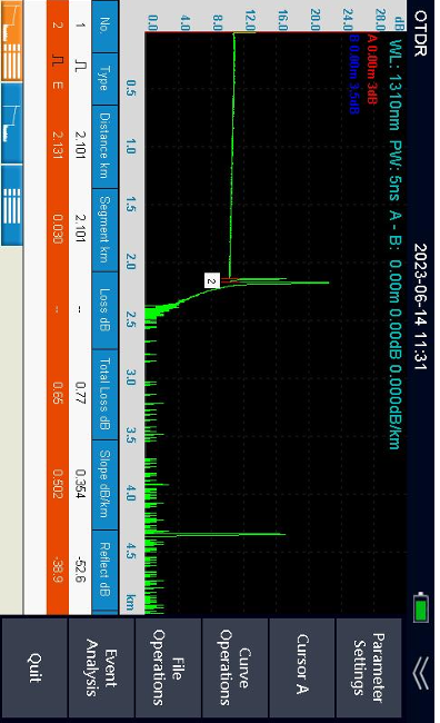
setting . I n the OTDR testing page , top part is current testing parameters
for quick view,
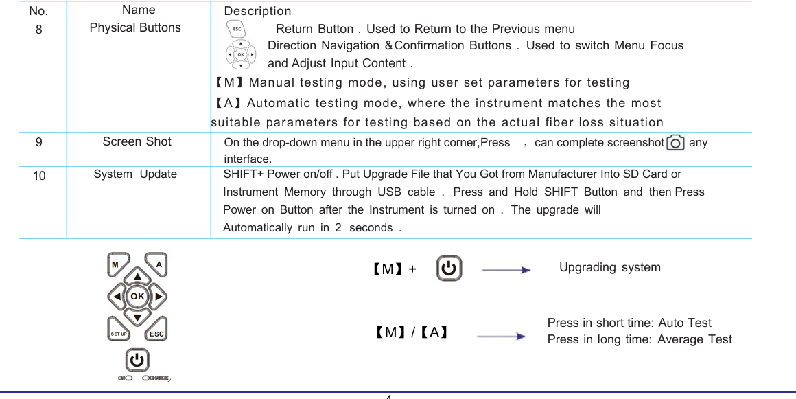
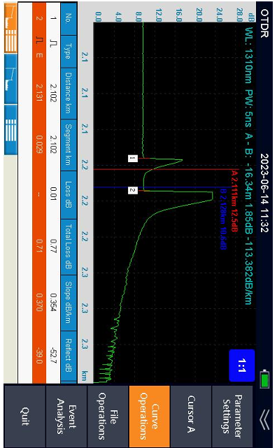
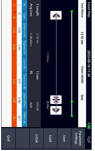
Name Description
WL Wavelength . It is for current test only
PW Pulse width . It is for current test only
Y
A
B
Vertical axis scale in dB .
T he position of cursor A in distance & loss at current position
T he position of cursor B in distance & loss at current position
A-B
Distance between A and B . Loss Value between A and B
Middle part is curve that OTDR created . Press [LEFT] or [RIGHT] button
to move position of Cursor A and Cursor B for curve analysis .
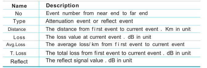
Bottom part is Event List . A ll events are listed on a table
 Start your First OTDR Testing
Event List
If you can not select event table , press [SHIFT] button . Then you can
select event column by [UP] or [DOWN] button .
Move Curve
You can move entire curve to left , right , up or down by [SHIFT] button ,
[LEFT] , [RIGHT] , [UP] or [DOWN] button . If you can not move curve , press
[ SHIFT] button repeatly until you can see icon which indicates operation
method at top of screen .
Zoom in or out
You can zoom in or out curve by [SHIFT] button , [LEFT] , [RIGHT] , [UP] or
[DOWN] button . If you can not zoom in or out curve , press [SHIFT] button
repeatly until you can see icon which indicates method at top of screen
To Operate OTDR Testing Results
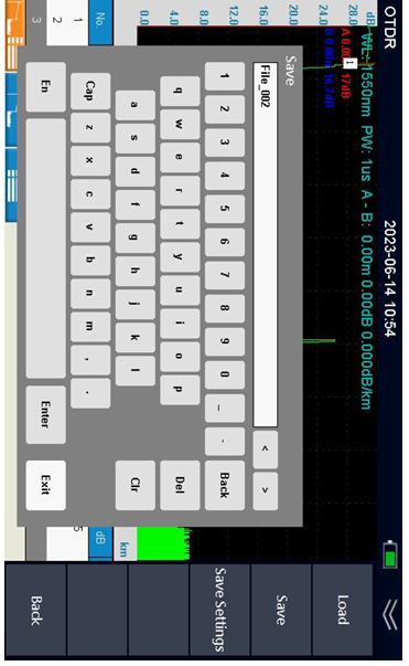
To save OTDR Testing Results
After testing done , press [SHIFT] button to select setting , then press
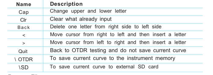
[RIGHT] button to select save menu , and press [OK] button . Input a name
for the current curve by operating [LEFT] or [RIGHT] button
Rename File
Using [SHIFT] and [RIGHT] button to select File menu , then press [OK]
button to enter file management . Press [SHIFT] button and [DOWN]
button to select a file that you are going to change name . Press [OK] to
change its name .
Delete File
Using [UP] button and [DOWN] button to select a file , then by [SHIFT]
button and [RIGHT] button to select Delete menu , press [OK] .
To save testing result
Start your First Event map TestingEvent List
If you can not select event table , press [SHIFT] button . Then you can
select event column by [UP] or [DOWN] button
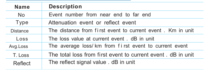
View OTDR curve
. If you want to view the OTDR curve, you can press the [OTDR] button to enter
the OTDR curve display
 Optical Light Source
Turn on Light Source
After enter the light source function , select start menu by [LEFT]
button and [RIGHT] button . Press [OK] to turn on the light source . Once
turned on , laser icon at middle of screen will be changed in red . Once
laser source is turned off , the color will be back in gray.
Change Wavelength
Press [RIGHT] button to select wave menu and press [OK] button to
change wavelength . Wavelength is according to model# of the Smart
OTDR.
Change Frequency
Press [RIGHT] button to select Frequency menu and press [OK] button to
change frequency. The optional frequency is CW, 270Hz , 330Hz , 1 k Hz ,
2kHz.
Quit
Press [RIGHT] button to select Quit menu and press [OK] button to come
back main page .
Warning:
Do not look at light source port .
Laser is not visible , but it is dangerous for human
 Optical Power Meter
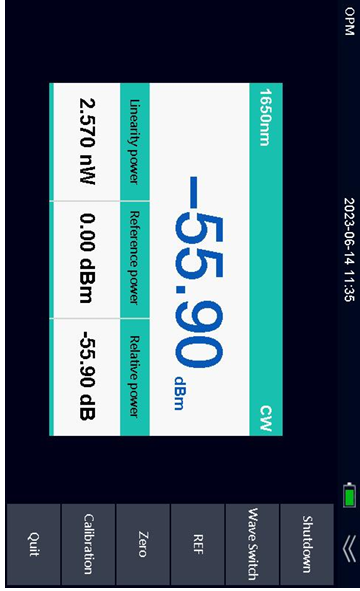
Turn on optical power meter
Once you enter the function , optical power meter is turned on .
Change Wavelength
By [RIGHT] button to select wave menu , press [OK] button to change
wavelength . The optional wavelength is 850nm , 1300nm , 1310nm ,
1490nm , 1550nm and 1625nm .
Set REF
By [RIGHT] button to select REF menu , press [OK] button to set current
optical power value to a reference .
Set Zero
By [RIGHT] button to select Zero menu , press [OK] button to set current
optical power value to zero .
Quit
Press [RIGHT] button to select Quit menu and press [OK] button to come
back main page
Optical Power Meter
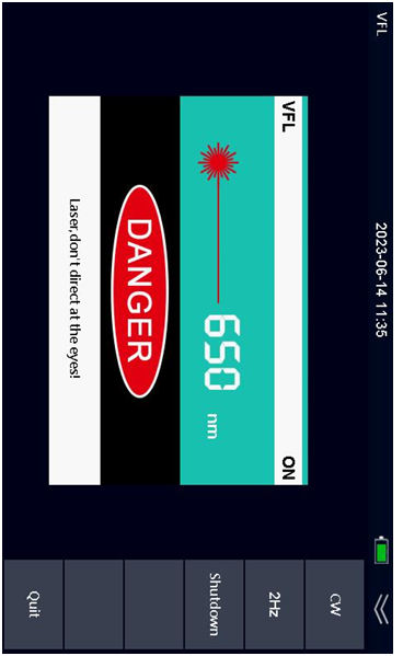
Visual Fault LocatorVFL Mode
The Visual Fault Locator supports 2 modes . One is CW, the other is 2Hz
Flash . Press [RIGHT] button to select CW, then press [OK] to turn on CW
mode . Press [RIGHT] button to select 2Hz menu , then press [OK] to turn
on flash mode at 2Hz frequency.
Turn off Visual Fault Locator
W hen you are going to turn off the Visual Fault Locator function , select
start menu by [RIGHT] button . Press [OK] to turn off the visual fault
locator. Once turned off , laser icon at middle of screen will be changed in
gray. Once laser source is turned on , the color will be back in red .
Quit
Press [RIGHT] button to select Quit menu and press [OK] button to come
back main page .
Warning:
Do not look at light source port .
Laser is not visible , but it is dangerous for human .
Visual Fault Locator
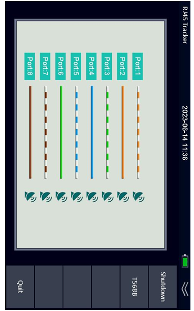
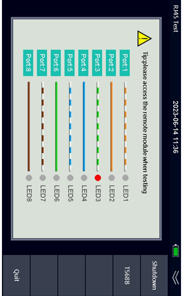
RJ45 Cable TestingTurn on RJ45 cable Testing
After enter the RJ45 testing function , select start menu by [LEFT]
button and [RIGHT] button . Press [OK] to turn on the RJ45 testing
function .
RJ45 Cable Sequence Testing
Connect RJ45 cable into the instrument . At bottom of the instrument ,
there is a block . Take it out from the instrument and plug RJ45 cable into
the block . You can see the cable sequence by check port number and
LED number. Press [RIGHT] button to select T568B menu and press [OK]
button to change T568B and T568A standard
RJ45 Cable Testing
RJ45 Cable Tracking
Press [RIGHT] button to select Tracker menu , then press [OK] button . The
instrument will send signal to RJ45 cable . You can search for RJ45 cable
by signal receiver.
Quit
Press [RIGHT] button to select Quit menu and press [OK] button to come
back main page